27 Jul Weld Representation in FEA
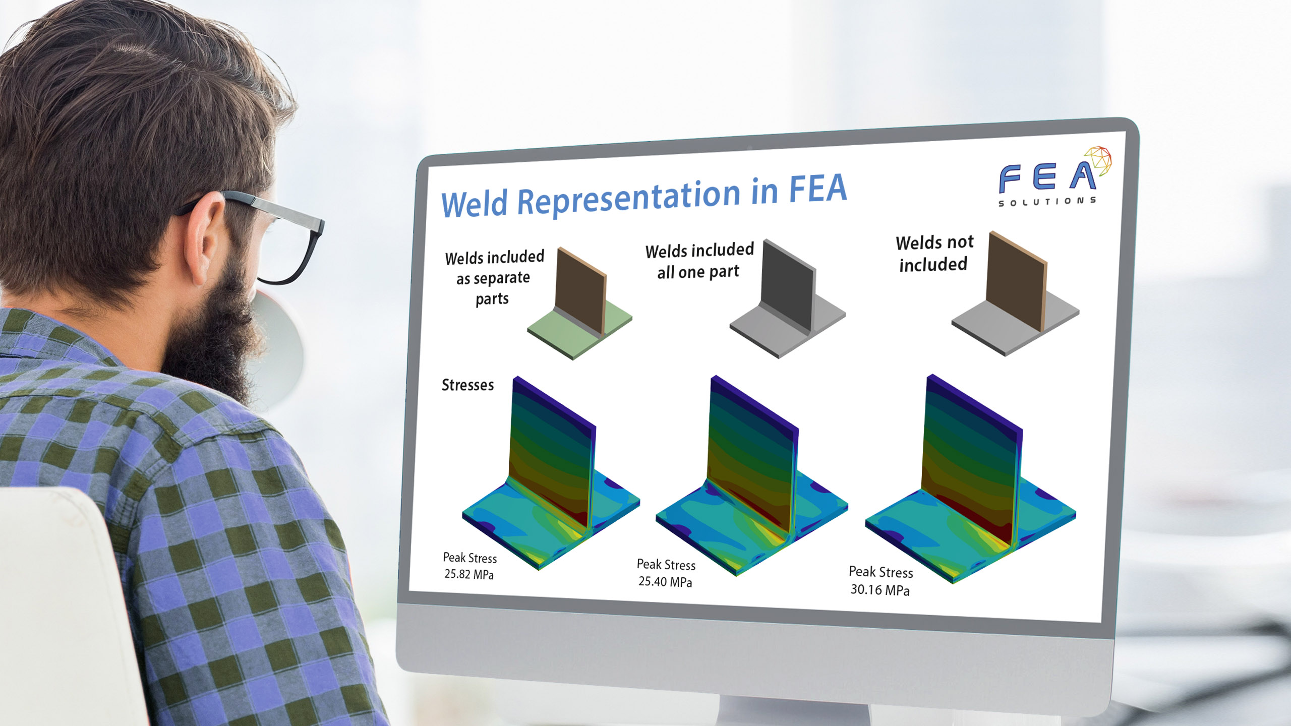
When a welded component is simulated in FEA, there are two ways to represent the welds:
– Treating the welded components as a single part.
– Modelling the weld seam in detail.
As in most cases the weld geometry is small compared to the overall size of the structure to be analysed, treating two welded components as a single part and not modelling the actual geometry of the seam is often required to avoid a high element count, driven by the small mesh size required to realistically represent the weld. In this case, the two welded bodies will be joined by a linear structural contact (https://fea-solutions.co.uk/linear-structural-contact/).
This approach assumes that in reality the weld is full penetration, and that the weld material (filler wire) properties are the same as those of the base material.
Including the weld in detail requires:
– Knowing the weld seam geometry in detail, which is often difficult because it is the result of the welding process.
– Knowing the material properties of the filler wire after cooling, and possibly knowing the extend of the Heat Affected Zone (HAZ) (https://fea-solutions.co.uk/heat-affected-zone/).
– Knowing, or simulating, the residual stresses resulting from the welding process.
Although all of the above can be covered by FEA, in most cases it is not economical to do so. Instead, the welded components are represented as a single part. To compensate this simplification, the stress allowables could be reduced in the weld area, although the simplification itself often results in conservatively high stresses.
It should be noted that the simplified weld representation, in particular of fillet welds, might result in stress singularities (https://fea-solutions.co.uk/stress-singularities/) which would locally invalidate the FEA results.
Please call us today on +44 (0)1202 798991 for any engineering analysis requirements you might have.