19 Jan Global, Local and Element Coordinate Systems
In FEA, different coordinate systems (COS) are used depending on the application.
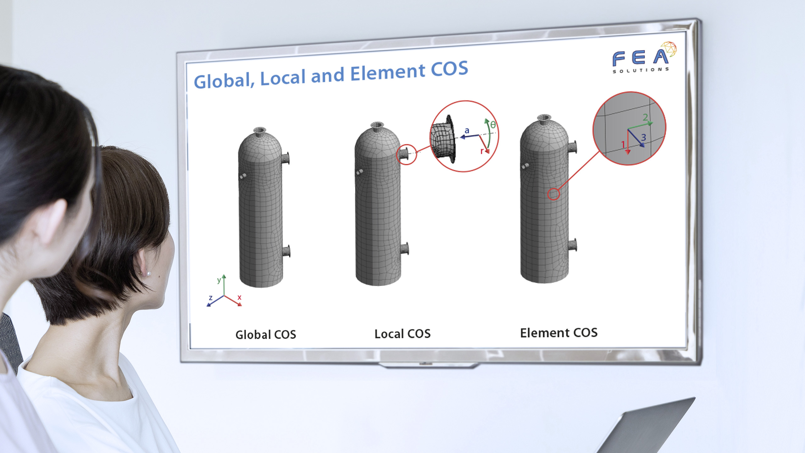
The global COS in FEA is always the Cartesian (https://fea-solutions.co.uk/coordinate-systems/) COS, as all matrix calculations (stiffness, mass and damping) are done using this system.
A local COS can then be used when it is advantageous. For example, when using a pie-cut (https://fea-solutions.co.uk/mirror-symmetry/) symmetry model (https://fea-solutions.co.uk/symmetry/), a local COS is used to define to symmetry planes of the pie-cut to apply the symmetry boundary condition.
A local COS can be used to define any loads or constraints. For example, a pipe that is supported by a clamp can be constrained only in the radial direction by using a local cylindrical COS.
Results from analyses can be displayed in the global or the local COS, depending on the result in question. Deformations, for example, may be more useful if displayed in a cylindrical COS for a column vessel, with the magnitudes shown in radial, axial and circumferential direction rather than in x, y and z direction.
A local COS can be Cartesian, cylindrical or spherical.
In FEA, each element has its own COS. Displacements at each node are calculated in the global COS (https://fea-solutions.co.uk/nodal-stress-calculation/) and then used to find the element results, which are transformed to the element COS. The element COS is generated automatically by the FEA solver and will often use notation different to the global system, e.g. x,y,z for the global but 1,2,3 for the element system.
For orthotropic materials, the element COS is used to define the properties. Orthotropic material properties are often used when modelling composite parts, as they have different stiffness in two orthogonal directions.
The element COS will depend on the type of element being used in the analysis, with surface elements (https://fea-solutions.co.uk/surface-elements/) by definition having the 3 direction out of plane of the surface, and beam elements (https://fea-solutions.co.uk/line-elements/) having the 3 direction along the beam length. It is always a Cartesian COS.
Please call us today on +44 (0)1202 798991 for any engineering analysis requirements you might have.