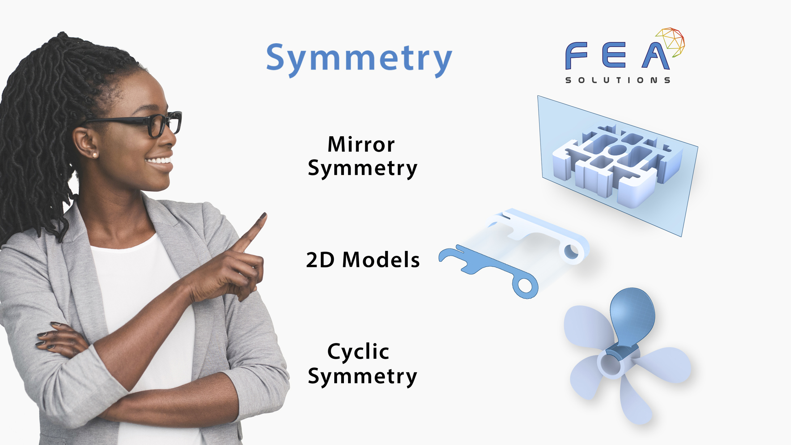
Author: Constance Fischer

Simulation models can be simplified using Symmetry. This is only appropriate if the geometry as well as the loads are symmetrical in the same direction. There are three different types of Symmetry. Most common is Mirror Symmetry (https://fea-solutions.co.uk/mirror-symmetry/), but 2D simplifications (https://fea-solutions.co.uk/2d-models/) and cyclic symmetry (https://fea-solutions.co.uk/cyclic-symmetry/)...

Solid Elements can have anywhere between 4 corner nodes (for Tetrahedral Elements) and 8 corner nodes (for Hexahedral Elements). Solid Elements are used where all three dimensions of the part are comparable. They are used on most complex parts. Anything that is machined, cast or forged...

Surface Elements consist of 3 or 4 corner nodes, and the mid-surface of a part. Once created, the FEA software requires the surface thickness to be assigned. Surface Elements are used when two part dimensions are much greater than the third dimension. They are used when...

Line Elements consist of a starting point (node), an endpoint and the connectivity between the two which can be visualised by a line in 3D space. Line Elements are suitable to represent beams and trusses, but also for more complex parts such as springs and dampers....

There are different types of Finite Elements used in FEA, with each having a different underlying mathematical model. The most commonly used element types are: Line Elements (also called 1D Elements). (see: https://fea-solutions.co.uk/line-elements/) Surface Elements (also called Planar Elements or 2D Elements). (see: https://fea-solutions.co.uk/surface-elements/) Solid Elements (also...

FEA models are described by a set of Nodes. Nodes are characteristic points which are defined by their coordinates in space. These Nodes are then connected by mathematical equations called Shape Functions. Together with the Element Formulation (“element type”), the applicable Material Law (e.g. Law of Elasticity...

Non-linear contact is one of the three non-linear behaviours in structural analysis, see: (https://fea-solutions.co.uk/non-linear-behaviour/) Non-linear contact is required where the load path between parts of an assembly is affected by the load direction. A typical example where non-linear contact has to be taken into account is a...

Large deformation, or geometric non-linearity, is one of the three non-linear behaviours in structural analysis, see: (https://fea-solutions.co.uk/non-linear-behaviour/) In linear analysis, the equilibrium of forces (and moments) is established on the undeformed structure. That means, although one of the results of the FEA are deformations, the calculation...

Non-linear material behaviour is one of the three non-linear behaviours in structural analysis, see: (https://fea-solutions.co.uk/non-linear-behaviour/) When talking about non-linear materials, most people think about plastic behaviour. This is however just one of several non-linear materials. They are: Plasticity This describes the non-reversible deformation of a solid part, see:...

Numerical simulation, including FEA, is well suited to realistically predict non-linear behaviour of physical phenomena. Looking just at structural analysis, there are three different types of non-linear behaviour. They are: Non-Linear Material This has to be considered if the material doesn't behave linear-elastically. Read more about these...