14 Dec Acoustic Transmission Loss
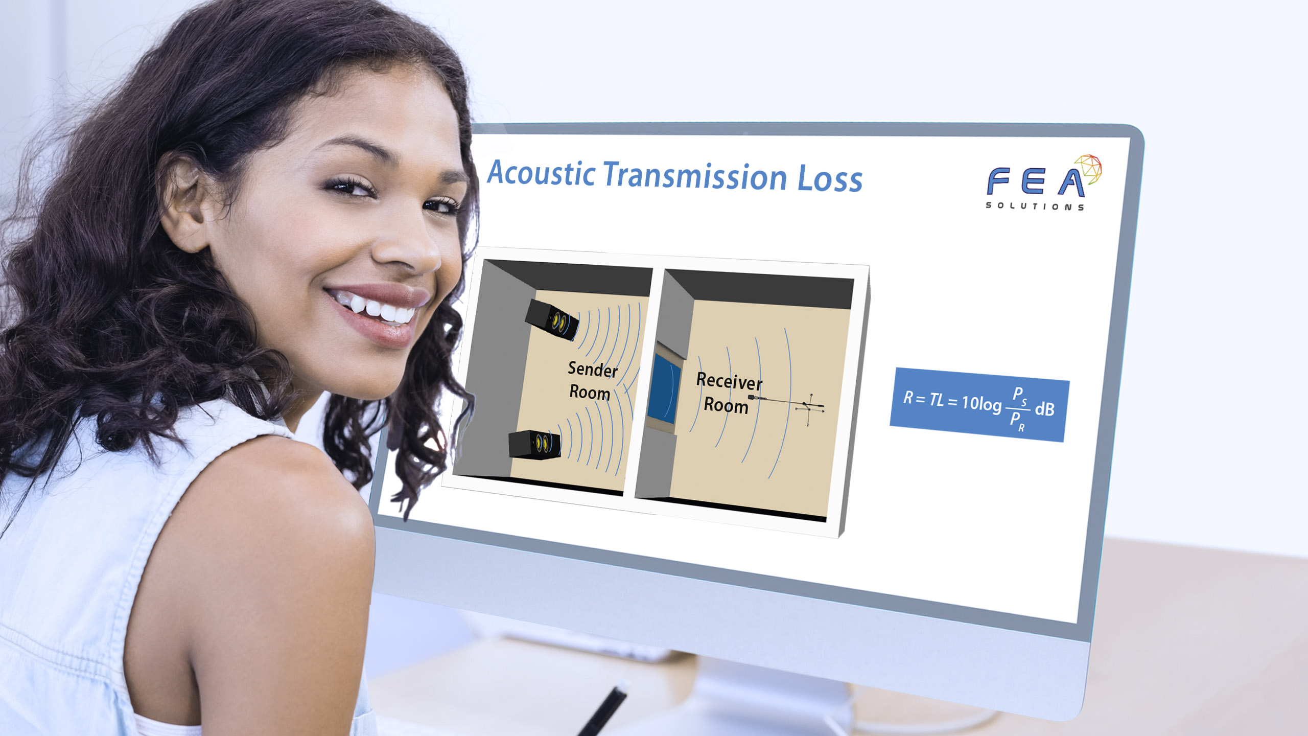
In acoustics (https://fea-solutions.co.uk/acoustics/), transmission loss is defined as the ratio between the power send and power received. In physical tests this is typically performed by having a sender room and a receiver room, with the item being tested (for example a door) installed between the two rooms. The transmission loss is calculated form the acoustic power recorded in both rooms. The disadvantage of doing such physical tests is that results will depend on the characteristics of the rooms.
In FEA (https://fea-solutions.co.uk/what-is-fea/) however, special boundary conditions can be used, meaning the rooms do not need to be analysed, which not only makes performing the analysis simpler, but also makes the results independent of the room.
On the sender side of the object to be analysed, a Diffuse Sound Field boundary condition is applied, which simulates sound coming onto the surface from all directions, as it would occur in reality. On the receiver side of the object to be analysed, a Far-field Radiation Surface boundary condition is applied, which defines the sound that would be radiated from the surface.
Transmission loss typically varies over frequency, with the frequency range defined in the applicable engineering standard, e.g. BSEN ISO 10140. The transmission loss has the unit of decibels (dB).
Please call us today on +44 (0)1202 798991 for any engineering analysis requirements you might have.